 NOAA Fairbanks Autonomous Ground
Station
NOAA Fairbanks Autonomous Ground
Station
NOAA Fairbanks Autonomous Ground
Station
by Mike Anderson, Peter Militch, Hugh Pickens
AlliedSignal Technical Services
Technical Paper presented at the International Telemetering Conference in 1999
ABSTRACT
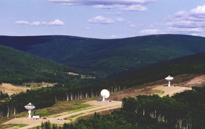
In 1998, AlliedSignal Technical Services (ATSC) installed three fully autonomous 13-meter satellite tracking systems for the Integrated Program Office of the National Oceanic and Atmospheric Administration (NOAA) at the Command and Data Acquisition Station near Fairbanks, Alaska. These systems track and command NOAA Polar Orbiting Weather Satellites and Defense Meteorological Satellites and download weather data from them.
Each tracking system operates for extended periods of time with little intervention other than periodic scheduling contacts. Schedule execution initiates equipment configuration, including establishing the RF communications link to the satellite. Station autonomy is achieved through use of a robust scheduler that permits remote users and the System Administrator to request pass activities for any of the supported missions. Spacecraft in the mission set are scheduled for normal operations according to the priority they have been assigned. Once the scheduler resolves conflicts, it builds a human-readable control script that executes all required support activities. Pass adds or deletes generate new schedule scripts and can be performed in seconds.
The systems can be configured to support CCSDS and TDM telemetry processing, but the units installed at Fairbanks required only telemetry and command through-put capabilities. Received telemetry data is buffered on disk-storage for immediate, post-pass playback, and also on tape for long-term archiving purposes. The system can autonomously support up to 20 spacecraft with 5 different configuration setups each. L-Band, S-Band and X-Band frequencies are supported.
KEY WORDS
Satellite tracking station, satellite ground station, satellite ground system, satellite ground terminal, ground segment, spacecraft commanding, autonomous, monitor and control, scheduling
SYSTEM OVERVIEW
Each system includes a 13-meter elevation over azimuth antenna with a 7 degree tilt and dual polarization auto-tracking feeds. .The G/T is 19 dB/ÆK at L-Band, 23 dB/K at S-Band and 34 dB/ÆK at X-Band. Transmitter EIRP is 68 dBW. The system supports a 1750 to 2120 MHz uplink band. The receive bands are 1670 to 1710 MHz, 2200 to 2400 MHz and 7.6 to 8.4 Ghz. The L/S-Band RF subsystem employs a polarization diversity feed with optimal ratio combining and supports FM, PM, BPSK and QPSK modulation types with up to 5 MBps data rates. The X-Band feed provides switchable polarization selection and sufficient bandwidth to accommodate current and future high-rate, remote sensing satellites.
Communications links between the antenna and the operations building for the L-Band, S-Band and X-Band signals, command and command verification data, equipment monitor and control, and timing signals are over a fiber optic link.
Each system includes five strings of dual receivers and diversity combiners for L/S-Band signal processing. The receivers are configured with dual band tuners to cover the required L and S-Band frequency ranges. Diversity combiners assure excellent performance for all combinations of RHCP, LHCP or linear signal conditions. Discrete bit synchronizers are provided, permitting operations personnel to rapidly configure the complete receive processing subsystem manually should the need arise. A failure of any receiver or bit synchronizer can be easily remedied by substituting a spare unit.
Dual tracking receivers are located in the antenna pedestal. Two receivers provide the required auto-tracking performance for all receive signal conditions. These receivers are Datron Universal Track Receivers.. L/S-Band transmit capability is provided by a solid state transmitter, offering high reliability and simplicity of operations.
The command verification subsystem consists of a directional coupler at the output of the transmitter to sample any transmitted signals. The sampled signal is mixed down to 230 MHz at the antenna. This signal is received and demodulated by a VME form-factor receiver for return to the operations building. A signal generator is used as an exciter for both L-Band and S-Band operations. The generator includes a built-in PRN generator for system loop-back performance testing.
A digital recorder simultaneously records data from all five receive channels. Both tape and disk storage is used. The disk allows rapid queuing of data for playback in either the forward or reverse direction. Real-time and playback telemetry, and real-time commands, are routed to and from the individual systems automatically under schedule control.
The central feature of this system is that all the equipment described above is monitored and controlled from a low-cost, high performance workstation. This workstation and the ground station automation software it executes provide for both local or remote monitor and control capability, and for fully automated antenna operations. The remainder of this paper explains what the ground station automation software does and how it works.
GROUND STATION AUTOMATION OVERVIEW
The monitor and control package used to automate the ground station is the Epoch 2000 COTS software package from Integral Systems. The software provides all required ground equipment monitor and control capabilities. All configuration data is managed in an Oracle ground station automation data base.
The data base allows the ground station to be configured for new satellites and new missions without extensive software modifications. The station automation software runs on a Unix Administrative Workstation. The workstation is a Pentium PC running at 200 MHz, with 128 Mbytes of memory, 2 Gbytes of hard disk storage, plus keyboard, mouse, and a 20" color monitor.
MANUAL CONTROL MODE
Manual control mode provides complete local monitor and control capabilities through a graphical user interface shown in Exhibit 1. All of the hardware reconfiguration capabilities which can be accomplished via equipment front panel switches can be accomplished directly at the Administrative Workstation, providing a central point of management for the entire system. There are several different mechanisms for reconfiguring the hardware using the ground station automation software directives. First of all, control directives can be manually typed in directly on the user input line which appears in the header of every display page on the workstation.

Exhibit 1. Sample Ground Station Automation Display
In general, for every equipment control state and system configuration option there is a corresponding control directive. A directive is simply an ASCII keyword which tells the system how to reconfigure a given item of equipment. The control directive definitions and configuration options are defined through the ground station automation database utility, which is bundled with the standard automation software package. This allows new hardware and new configurations to be added with a minimum of software impact.
The ground station automation software provides an input line for control directives, as well as tabular and graphical displays for monitoring station status and the station event log. Directives may also be issued via user-programmable function keys and user-definable "hot" buttons, reducing the typing required to a single keystroke or mouse click. Directives may also be issued by dragging the mouse through a series of hierarchical menus organized by system and subsystem.
On input, the ground station automation software checks each directive for proper syntax, keyword, and arguments. The directive is then decoded and issued to the hardware for execution .
As each directive is input and processed, the software writes it into the station log. The station log contains a time-sequential list of all significant station activity, including hardware equipment configuration changes, operational mode changes, system status and event messages, and alarm/event messages. Each log entry is stamped with station time (as received via the time code reader in the Admin Workstation) and message source (e.g., hardware component, software process). The user interface (see below) supplies a view window into the station log which can be scrolled backwards and forwards in time, providing the operators with complete visibility into all of the significant station activities. Exhibit 2 provides a sample display.

Exhibit 2. Scrollable Event Log
All of the equipment status information, as well as the configuration of the software itself, may be monitored and controlled via the ground station automation software on the Administrative Workstation. The M&C user interface provides full adherence to OSF Motif open systems standards. Our interface follows industry standard design principles to ensure ease of use.
The equipment status parameters themselves can be displayed in a variety of formats, including ASCII text, graphs, polar plots, bar charts, and gauges. A set of pre-defined display pages is available to users, and users can easily define their own custom pages. Exhibit 3 provides a sample display for manual antenna control and monitoring.

Exhibit 3. Antenna Control Interface
The Administrative Workstation supports multiple simultaneous local and remote login's via the SUN Solaris operating system and X-Windows so that multiple workstations can be used to support operations, both locally at the Fairbanks site and remotely at SOCC and/or other sites. Each login is a separate X client, running its own copy of the X-Windows Administrative Interface.
LOCAL AUTOMATED MODE
The ground station automation software provides a built-in procedure language which can provide fully automatic local operations. In Local Automated Mode, the system operation is conceptually the same as in Local Manual Mode, with the addition of one key element: STOL (System Test And Operations Language). STOL is an interpreted procedure language hat supports features such as: procedure flow control such as DO-WHILE, IF-THEN-ELSE, and GOTO, calls to other STOL procedures, directives to the automation software processes, including directives to configure ground equipment, directives to send spacecraft commands, arithmetic, logical, and string expressions, calls to built-in functions, calls to execute UNIX scripts or start software processes, relative and absolute time tags. Exhibit 4 provides a sample STOL procedure. This high-level language allows automation of all Fairbanks hardware and software configuration operations.

Exhibit 4. STOL Procedure
STOL is an existing component of the ground station automation software package. Fully automatic local operations are provided simply by writing procedures for each of the routine operational activities, such as pre-pass setup, real-time pass processing, post-pass termination, and offline troubleshooting/diagnostics. The appropriate procedure may then be invoked by typing in its name, selecting it from a menu list, pressing a designated function key, or clicking on a hot button.
REMOTE AUTOMATED MODE
The automated ground station provides a complete, built-in scheduling system which supports fully-automated operations from a remote site (e.g., SOCC). Key features of the scheduling system include: automatic allocation of antenna coverage across multiple missions, automatic conflict resolution, automatic pre-pass, pass, and post-pass reconfiguration according to pre-defined database specifications, automatic ingest and propagation of orbital elements and automatic generation and selection of candidate passes for coverage. The scheduler supports up to 20 different simultaneous missions (satellites), each with up to 5 different pre-defined configuration options for support requirements.
There are two basic inputs into the scheduling process: Orbital elements and pass coverage requests. The orbital elements can be hand entered in any of approximately one dozen different coordinate systems including both the NORAD standard used by DMSP and the NASA IIRV standard used by NOAA. The system can also be configured to automatically ingest NORAD or IIRV types from a remote server. The input frequency, propagation interval, remote server domain name, and pathname for the element files are user-reconfigurable via the database.
The retrieved elements are then be propagated automatically to determine the contact information (e.g., start time, stop time, max el, etc.) for all possible passes for each mission supported. This propagation is performed by OASYS (Orbit Analysis System), which is a COTS package for general orbit support provided by Integral Systems. The orbital analysis software provides a full spectrum of orbit analysis capabilities, including: orbit determination, high-fidelity numerical orbit propagation, NORAD SGP-4 semi-analytic orbit propagation, generation of satellite and station geometry reports (e.g., position, velocity, subpoint, range, Doppler, etc.), generation of satellite and station event reports (e.g., AOS, LOS) and orbit maneuver planning
The outputs from the orbital analysis software processing consist of sets of tracking elements for each satellite mission defined in the database. These are automatically downloaded to the antenna controller during the pre-pass configuration processing at the start of each pass. This guarantees that the antenna controller always has the freshest elements available for antenna pre-positioning and open loop track operations.

Exhibit 5. Pass Selection Window
The orbital analysis software also outputs a complete set of candidate pass parameters for all of the supported satellites. This information is used to drive the Pass Selection window, which is the mechanism for getting the other primary input to the scheduling process; namely, the user's pass coverage requests. The Pass Selection window shown in Exhibit 5 is accessible locally at the Admin Workstation or remotely (e.g., at SOCC) via X-Windows. It lists all of the potential passes for all the satellite missions defined in the data base in chronological order, along with the predicted time of Acquisition of Signal (AOS), Loss of Signal (LOS), and maximum elevation.
The software allows the user to request coverage for single or multiple passes with a click of the mouse. To request coverage, the user simply highlights the desired contacts with the mouse and clicks the "Submit" button. Schedule requests are then automatically generated for those passes and satellites. The user may optionally specify one of up to 5 pre-defined pass configurations for each satellite's passes for non-nominal or special coverage requests; else, the default configuration for each satellite is used automatically.
Schedule requests are nominally submitted over a 7 day cycle (the cycle is reconfigurable via the database). Multiple requests may be submitted at essentially any point in the cycle. Then, at a user-configurable time interval (default 7 days), the software automatically invokes the schedule generation process. This process first builds a timeline of requested passes. The process input consists of all schedule requests, schedule related database parameters, and the satellite orbital information prepared by the orbital analysis software.
Each of up to 20 satellites has a unique priority, as assigned by the ground station administrator in the database. Conflict resolution is then performed on the requests in a strict-priority basis - that is, the highest priority satellite gets all of its pass requests, followed by the next highest, and so on. The end result is a conflict-free set of passes for all the satellites which can be accommodated given the current contact geometry.
SCHEDULE EXECUTION
Once conflict resolution has been performed, two output files are created: a Schedule Summary File and a Weekly Schedule File. The Schedule Summary File is a concise ASCII description of the weekly schedule, listing all passes and their associated parameters. The Weekly Schedule is also an ASCII file containing STOL-compatible constructs which can be executed directly by the ground station automation software. This file contains everything necessary to execute automatically for an entire week, including calls to a standard library of STOL procedures. The procedure library encapsulates frequently performed functions, e.g., standard ground equipment setup, pre-pass configuration sequences, etc. Most of the weekly schedule directives are calls to procedures in the STOL procedure library - the same STOL library procedures used in the Local Automated Mode described previously. Thus, the weekly schedule is more concerned with 'what to do', leaving the 'how' to procedures in the library. This allows implementation details of a particular function, e.g., pre-pass setup, to be encapsulated within a procedure. Any changes to how that function should be performed can then be made in the procedure, without affecting the rest of the system.
Upon completion the new schedule is logically appended to the old schedule, ensuring continuous operations with no gaps at the overlaps (the append is "logical" rather than physical to keep the cumulative schedule file from growing arbitrarily large). Once the schedule is created, it may be inspected through a dedicated schedule display window (either locally or remotely via X-Windows). The schedule window also allows authorized users to manually modify the schedule in several ways, including: addition of new passes in the gaps between the scheduled passes, cancellation of a scheduled pass and modification of pass parameters (start and stop times, specified database configuration). These capabilities are provided to support non-routine operations and anomalies and are not necessary in normal automated operations.
Schedule execution is normally be continuous and automatic, requiring no operator intervention. The system transitions autonomously between satellites and passes. A typical pass scenario is as follows (all times and events are reconfigurable):
For emergency situations, the ground station automation software provides the system administrator with a method for suspending the current schedule, and running an unscheduled pass. This can be done through the standard user interface. Through this interface, an administrator can view schedule directives being executed, pause a schedule, bring up a new satellite database and reconfigure ground equipment, run part or all of other STOL procedures, enter directives manually at the keyboard, and resume a schedule at any point. Again, this can be accomplished either locally at the Admin Workstation or remotely via X-Windows.
Return to Projects Page here.